Electrical contracting in Glasgow and Renfrewshire - Highlighting the new regulations, installations and current matters to do with all aspects of Electrical contracting - Iain Jamieson Wes electrical
Search This Blog
Showing posts with label electricians mosspark. Show all posts
Showing posts with label electricians mosspark. Show all posts
After I attended a briefing and update session today by the NICEIC I can report on some of the main points of interest to property owners:-
Between January and July 2015 electrical installations work undertaken can comply with either the old or the new regulations. From July 2015 the new regulations will apply except in one regard in respect of replacement or new Consumer Units. Any electrical contractor engaged should by January be conversant with the new regulations.
Not unexpectedly the changes to regulations are there mainly to improve safety to persons and property. A few of the changes are to better align our regulations alongside common European regulations.
For home owners, from January 2016 at the latest, the main change will be a slightly different construction for Consumer Units (aka Fuse Box). Consumer Units will need to be of a fire resistance construction, in other words steel. They may not be quite so pretty and the method for the cables entering the Consumer Unit may not be so flexible or pretty either. We shall have to wait and see what the manufacturing industry comes up with over time as they accommodate this new requirements. I would forecast that prices for these new steel Consumer Units will be more expensive to manufacture and will take a little longer to install. It also means that from mid 2014 there could be a flood of 3rd Amendment Regulation non compliant Consumer Units available at knock down prices.
For commercial businesses, schools, colleges and government buildings there will be stricter requirements for additional protection against electric shock on socket outlet circuits by increasing the use of safety devices called RCDs. It will be a useful change in increasing safety but it does mean perhaps increased costs and in some cases a different approach to design circuits for computer equipment in offices and education establishments.
The will be more focus of design, inspection and testing of control circuits such as those used for central heating systems. This could present some challenges for Gas/Oil heating system engineers who may in the future have to call in an electrician whereas previously they could have completed the wiring to control valves, controllers and thermostats themselves. This too will have cost implications on home owners.
The regulations for formal Inspection are changing a little as well. Enough require all new stationary and reference material for electrical contractors. Also new methods and adjustments to learn how to use for recording results.
Interestingly there is a new regulation that when Periodic Inspections and Tests (EICR)are being undertaken in Homes and Business Premises then inspection to some degree or another in accessible loft spaces is now required unless recorded as a reasonable non compliance. Previously the inspection of wiring in loft spaces was a reasonably accepted omission. This is certainly a safety improvement as I personally have found a fair number of safety issues with wiring in lofts.
Another change is the need to ensure cables that run above or across safe exit routes but be secured with supports that will resist heat/fire. This is to avoid fire fighters and escapees being tangled up in drooping wire when try to get out of fire damaged building. Apparently the Fire Fighters requested this changes because there had been several deaths because of this problem. To installing electricians this is a fairly easy requirement to meet by using metal type buckle clips or purpose designed cable retainers for use inside trunking.
In the new Regulations there will now be approximately 1500 individual regulations, and increase of several hundred compared to the current issue.
Here i have for you a blog about electrical consumer units you know the box that when you have no power it has usually tripped or the fuse wire needs replaced.....enjoy
All cables and connections to the consumer unit must be checked and tested by a qualified electrician. Do not attempt removal or replacement unless you are you are qualified to Part P regulation standards. It is also an offence to interfere with the seals on the electricity meter.
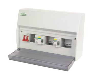
The modern consumer unit is the centre, or heart, of the wiring system in the home. The unit distributes the electricity, via fuses of one kind or another, to the different circuits in the house. The older fuse wires are being replaced gradually by their modern equivalent, the MCB or miniature circuit breaker.
The first one is a single load fuse board where the power coming in is taken through a double pole switch to a live bus bar. Each fuse, or MCB, is clipped onto a DIN bar and the "teeth" of the bus bar are inserted into the MCB's. The cables to the house circuits are connected to the other side of the MCB's. All of this is explained more thoroughly when we deal with the second type of unit, which is the split load unit. The photographs are of a split load fuse board. The ordinary consumer unit is exactly the same in principle without the RCD.
Consumer Unit
Under the 17th edition regulations it is required that every socket is protected by an RCD. This can be done in 3 ways.
A consumer unit can use an RCD as the main switch. This will protect all circuits but if the RCD trips, so do all circuits.
A dual RCD consumer unit can be fitted. This unit has one main switch, two RCDs and each circuit has it's own MCB. This allows the circuit to be divided into two, usually one upstairs, one down. This protects all areas including showers and cookers, but if one trips the other will ensure at least some lights and some sockets still work.
An RCBO consumer unit has one main switch but each circuit is protected by an RCBO which is a combination of an MCB and an RCD. This allows protection in full for all individual circuits and if one trips, all others will still work. As this option is expensive it is only usually used where space is tight for the enlargement of a consumer unit as has to happen when updating to a dual RCD unit.
Just as a matter of interest, DIN stands for Deutsche Industrie Norm and, originating in Germany, is any of a series of technical standards, used Internationally, to designate electrical connections, film speeds and paper sizes. Shown in the consumer unit casing above, it is a metal, pressed bar, to which the MCB's clip. They simply push on via a spring loaded lock at their back.
Split Load Board
A split load board is designed for total safety and incorporates an RCD (Residual Current Device, shown as E in the picture above) as well as the double pole switch (D).The split board shown here has one RCD and is a simple version to show the user how the board works.
An RCD is a manually operated isolator switch, but it is also an automatic safety device that will trip and cut off as soon as it senses an earth fault. There are a number of different ratings for current and sensitivities to current leakage available, so you will need to understand which are the appropriate ratings for your home. RCD's also work by detecting an imbalance between the Live and the Neutral conductors and this feature is a requirement for all Class 2 double insulated equipment.
As they are very sensitive, it is not practical to fit one RCD to protect the whole house. If a fault develops on one circuit, all circuits would be switched off immediately...This would, most often, leave you in the unnecessary position of having no lights or power. Because of this it actually contravenes the most recent (16th Edition) wiring regulations. This is easily prevented by using an RCD in conjunction with a main, double pole isolating switch so that it protects only some of the more vulnerable circuits. This then becomes a split load consumer unit and is shown above. The key to this photo is..
A: Neutral terminal block for the main isolating switch side of the unit
B: Neutral terminal block for RCD side of the unit
C: Earth terminal block (takes both sides of unit)
D: Main double pole isolating switch
E: Generally 80 - 100 Amp RCD with 30mA (milliamp) sensitivity
F: Neutral link cable from Main switch to terminal block
G: Live feed from main switch to RCD
H: Neutral link cable from main terminal block to RCD
I: Neutral link cable from RCD to RCD neutral terminal block
RCD's
The use of RCDs is necessary, on two occasions, to meet the wiring regulations. The first of these is to protect any socket which may be reasonably expected to supply equipment outside the house (Strimmers, lawn mowers, hedge trimmers, pond pumps, sheds, lights etc etc). This rule pretty much covers every single socket in the house so the ring main should be placed on the RCD protected side of the consumer unit.
RCDs have a test button which creates an earth leak with a resistor, and it is usually recommended that they are tested once a month. An information label near the consumer unit explains this The resistor passes more current than that required for tripping, and the duration of the test is not limited, so testing in this way does not provide proof that the unit is working to specification. RCDs can also be switched off manually and can take the place of the isolator switch in the consumer unit, if they break live and neutral.
The second condition applies to any circuits where an earth fault current is not sufficient to blow the fuse, or trip the switch, in the designated time allowance made in the regulations. This generally applies to higher Amp rated appliances (showers, cookers etc) but it should always be checked with an electrician as to which circuits need to be placed on the RCD side of the consumer unit.
MCB's
The Current ratings which MCBs are designated to deal with are now conforming to the international equivalent of our old imperial ratings. This standard is called the Renard current rating and supercedes the imperial ratings as far as MCBs are concerned. A 5 amp fuse can be replaced with a 6 amp MCB. A 15 amp fuse becomes a 16 amp MCB, a 20 amp fuse can be a 20 amp MCB, 30 amp fuse = 32 amp MCB and a 45 amp fuse must now be a 40 amp MCB.
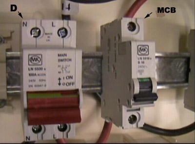
Consumer Unit with MCB and main double pole isolation switch
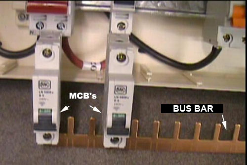
Consumer Unit with MCB's and Bus Bar
Top left shows the mains double pole isolating switch and an MCB clipped into place on the DIN bar. Top right shows two MCBs and the bus bar. When the MCBs are clipped onto the DIN bar, the bus bar is inserted into the live terminal at the bottom of the MCB. When screwed tight this gives live feed to all the MCBs.
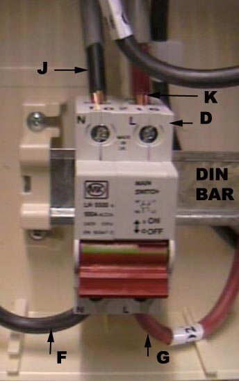
Main double pole isolation switch on din bar
live and neutral coming into the main double pole switch from the meter and earth terminal block
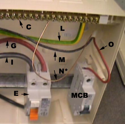
Top left shows the live (K) and neutral (J) coming into the main double pole switch from the meter. These cables are called tails, and in this instance, with this type of unit, are 16mm cables. This will vary and you should always check with a qualified electrician. Top left shows the earth cable from the meter (L). This screws into the earth terminal block.
Live connected to MCB with neutral going to RCD neutral terminal block
Top right of the above image shows how a circuit cable is introduced to the unit. In this case it is a 2.5mm cable for the ring main. The live (O) is fixed into the top of an MCB on the RCD side of the unit, while the neutral (M) goes to the RCD neutral terminal block. The earth (N*) (which has been left unsheathed for clarity ). Each circuit cable is fed into the consumer unit and connected to an MCB of the appropriate rating.
The recommended procedure for proving dead and safe isolation should be by use of a test lamp or two pole voltage detector as recommended in HSE Guidance Note GS38 regulations. Non-contact voltage indicators and multi-meters should not be used. The test instrument should be proved to be working on a known live source or proprietary proving unit before and after use. All phases of the supply and the neutral should be tested and proved dead before any work is commenced by a qualified electrician.
Test sequence and descriptions of test procedures.
The following tests are carried out with the main board / Consumers main switch isolated
1. Extenal earth fault loop impedance (ohms)
Reason: To establish that a good earth exists at the electrical installation in order for the remaining tests to go ahead.
Method: Disconnect the main earthing conductor from the main earthing terminal at the main distribution board. An earth fault loop impedance tester is connected at line and earth (main earthing conductor) at the supply side of the electrical installation and a test performed. Reconnect the main earthing conductor. The result is Ze and recorded on the test sheet. The prospective fault current is measured at the same time after the reconnection of the main earthing conductor at the main board.
2. Continuity of protective and equipotental bonding conductors
Reason: To check that all circuit protective conductors are continuous and are present at every electrical outlet / accessory on the circuit. Also to check that the main earthing conductor and main bonding conductors are continuous and correctly connected at the terminals.
Method 1: The line conductor is connected to the circuit protective conductor of the same circuit at the consumer unit and a measurement taken at ALL accesories on that circuit between line and c.p.c. The highest measurement obtained is recorded on the test report. Test result is R1 + R2. The line conductor and neutral conductor are then connected and the above repeated to obtain R1 + Rn
Method 2 (used for main earth and main bonding conductors): A wandering lead is connected to one end of the conductor to be tested and a measurement taken between the other end of this lead and the other end of the conductor. Test result is R2. During this test polarity can be checked as well. The continuity of the neutral conductor can also be checked to determine R2.
3. Continuity of ring final circuit conductors
Reason: This test ensures that all ring final circuits are indeed a continuous ring with no interconnects or breaks within it.
Method: The line, neutral and earth conductors of the circuit are identified and a measurement from one end to the other end of each is taken. These results are r1, r2 and rn. The incoming line conductor is then connected to the outgoing earth conductor and the outgoing line conductor is connected to the incoming earth conductor. A measurement is then taken at ALL socket outlets on the ring. The highest of which is recorded on the report. This result is R1+R2 for that circuit. The above is then repeated using the neutral conductor instead of the earth conductor. This test provides R1+Rn which does not need to be recorded on the report but is essential to check the circuit correctly.
4. Insulation Resisitance testing
Reason: This test checks whether the insulation around a cable is still intact and has not broken down over time or has been separated from the rest of the ring. It is a good indicator of the age of an installation.
Method: An insulation resistance tester is connected across line and neutral tails at the origin of the supply. 500V are then pumped down the conductors to see if any voltage leaks across from one conductor to the other. The same is then done for the line and earth and the earth and neutral conductors.
5. Polarity checks
Reason: To check that all accesories are correctly connected to line, neutral and earth and that all switches and circuit breakers are connected in the line conductor only.
Method: The method for this is the same as for continuity and is usually done at the same time by operating switches etc whilst conducting the test.
6. Earth electrode resistance
Reason: To make sure that any earth electrode used is of a sufficiently low impedance to allow the timely operation of the RCD protecting the installation.
Method: An earth fault loop impedance tester is connected between line and earth at the origin of the supply and a test performed. The result of which is considered the resistance of the electrode (Ra).
The following tests are carried out with the Consumers main switch switch in the on position
Reason: To verify polarity of supply authorities system.
Method: An approved voltage indicator shall be used or test lamp to GS38. Using the approved voltage indicator, one probe shall be placed on the incoming neutral, and the other on the incoming line conductor, on the main breaker. The indicator should show it is live. One probe shall now be placed on the CPC and the other on the incoming line conductor. The indicator should show it is live. A test shall be preformed between CPC & incoming neutral. The indicator should show that it is not live.
8. Earth fault loop impedance
Reason: This test is done at the furthest point on a circuit in order to make sure the impedance of the earth path is not too high even at the furthest point so that sufficient current will flow under fault conditions to take out the circuit breaker protecting the circuit.
Method: An earth fault loop impedance tester is connected to line and earth at the furthest point on the circuit and the test performed.
Reason: To make sure RCD's trip within the correct time
Method: An RCD tester is connected and a test at 1/2 times, 1 times and 5 times the trip current is performed on each side of the cycle and a time of trip obtained. Usually milli-seconds with the highest being recorded. The manual test button is then pressed.